In-Circuit Test (ICT)
of printed circuit boards (PCBs) or electronic devices
What is in-circuit testing (ICT)?
In-circuit testing (ICT) is a quality assurance step in the manufacturing of printed circuit boards or other electronic devices. The device under test (DUT) is contacted with a special test adapter and checked for manufacturing faults using a variety of electrical test procedures (e. g. short-circuit testing, resistance measurement, capacitance measurement). By comparing the actual test results with target values, defects like conductor path, soldering or press-in errors can be identified. In-circuit tests are limited to detecting structural defects but cannot draw conclusions about the DUTs functionality.
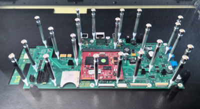
Fig.: printed circuit board (PCB) in an adapter for in-circuit tests
How are in-circuit tests carried out?
- To allow time-efficient and reliable testing, product designers stick to the principle “design for test” and equip DUTs with special test points.
- At the ICT test bench, these points are contacted with a test adapter that has been specifically designed or equipped for the DUT.
- The testing platform performs a variety of electrical tests, some of which may be carried out in parallel. In order to check single components within complex circuits, they are electrically isolated (so-called guarding). Sub tests of an ICT include:
- Short and open circuit tests
- Polarity tests
- Measurement of resistances, capacitances or inductances
- Digital tests (stimulation of input pins, monitoring of output pins)
- The results of the in-circuit test are compared to pre-defined target values (including a tolerance range). Deviations indicate manufacturing faults such as short circuits, open circuits, soldering, press-fitting or assembly errors resulting in the rejection of the DUT.
Differentiation from related testing methods
The in-circuit test must be distinguished from the following, related tests:
In-circuit test vs flying-probe test (ICT vs FPT)
The flying probe test (FPT) is also a purely electrical, function-independent test (and therefore an alternative to the ICT). The main difference is the way DUTs are contacted: Instead of a test adapter tailored to the DUT, a universal contacting system with few freely movable (“flying”) test needles is used. While ICT adapters contact many test points at the same time and tests can be performed in parallel, the FPT tester contacts test points and carries out tests in sequence.
In-circuit test vs functional test (ICT vs FCT)
In contrast to ICT and FPT, more complex tests are carried out evaluating the DUTs functionality according to a pre-defined specification. For example, digital signals can be sent to the DUT, or the sensors of the DUT can be interacted with. The testing system then analyses the reaction of the DUT. Functional testing is usually conducted in addition to ICT or FPT.
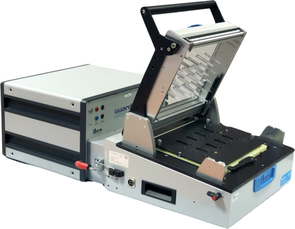
Fig.: Guardian FCT tester (also supports ICT) with attached test adapter
What are the requirements for in-circuit testing (ICT)?
For in-circuit testing, the following hardware and software is required:
- A test control unit (in-circuit tester), that reliably performs the desired electrical tests and logs results (e. g. the Guardian FCT tester which also supports in-circuit testing).
- A means of connection between the control unit and the DUT (test adapter), which allows time-efficient or even automated contacting of the DUT (e. g. test adapters from GTS Test Solutions).
- Real-time inspection software for programming, execution and automation of test sequences (e. g. WinGuard)
Do you need help with in-circuit testing?
Our competent and creative team gladly provides help and advice. Besides our in-house software and hardware for in-circuit testing, we offer integration services and turnkey test benches. We are looking forward to your contact enquiry!