Printed circuit board testing (PCB testing)
Definition, procedure, hardware and software
What is a printed circuit board test (PCB test)?
During a printed circuit board test (PCB test), PCBs are checked for production faults and correct functioning during or after their assembly. Electrical PCB tests include:
- Physical testing (e. g. in-circuit tests – ICT – or flying probe tests – FPT) during or after the assembly; PCB components are inspected for physical features (for example detection of faulty soldering by measuring electrical resistances or capacitances).
- During functional testing (FCT), PCBs are checked for correct functioning in context of their intended application. In contrast to ICT/FPT, functional testing can be performed no earlier than at the end of the manufacturing line of a functional unit (for example during an end of line test).
Besides electrical PCB testing, there are optical PCB tests. Printed circuit boards are photographed or X-rayed. Then, automated image processing software identifies production faults.

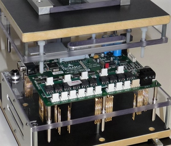
PCB ready to be contacted in a test adapter
How are electrical PCB tests performed?
- In order to allow for time-efficient and reliable PCB testing in industrial environments, product designers stick to the principle “design for test” and provide PCBs with special test points.
- These test points are contacted by test adapters right before testing (e. g. using needle bed adapters).
- The test system performs physical tests by measuring electrical resistances, capacitances etc. The results suggest whether production faults occured or not (more about in-circuit testing).
- During FCT, the test system exposes the PCB to different external influences (e. g. digital input signals, triggering of sensors or voltage dips) and examines the reactions of the PCB in real time (more about functional testing).
- The test system evaluates if the PCB has passed the inspection and informs the operator or control software.

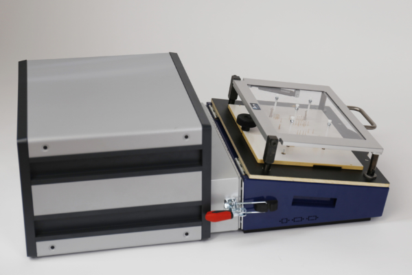
Guardian FCT tester with connected needle bed adapter of the series PA450
What is required for a PCB test?
In industrial environments, the following equipment is required for electrical PCB testing:
- A controler (e. g. FCT tester, ICT tester or FPT tester), which exposes the PCB under test to relevant influences and measures its reactions as well as physical parameters in real time (for example the Guardian FCT tester).
- A means of connection between the controller and the PCB under test (e. g. a test adapter), which allows for time-efficient and sometimes even fully automated contacting of the PCB (for example test adapters by GTS Test Solutions).
- Inspection software for programming and automating test sequences; must be capable of real-time test execution (for example WinGuard)
Do you need help with PCB testing?
Our competent and creative team gladly provides help and advice. Besides our in-house software and hardware for PCB testing, we offer integration services and turnkey test benches. We are looking forward to your contact enquiry!
Frequently asked questions
- A precise measuring and control unit capable of real-time applications (e. g. the Guardian FCT tester) in combination with appropriate inspection software (e. g. WinGuard)
- A means of contacting the PCB (e. g. test adapters by GTS Test Solutions)


